NIKIMAT


Amel Super Maramu 2000
|
Lofrans Tigres Windlass Overhaul Part 9: 10 Pictures from 74 to 83 Removing the Worm (shaft) from the electric motor, removing Thrust Ring, Thrust Bearing Spacer, seal, O Ring and key |
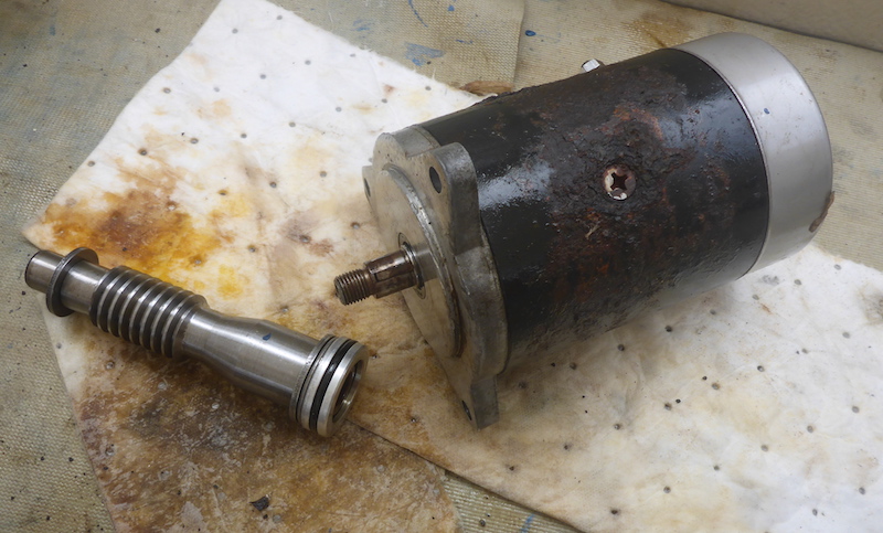
Picture 74
Now need to remove the Worm (shaft) (Part 483)
This will take me 4 hours
As I will discover later, this shaft has to come off for the reassembly
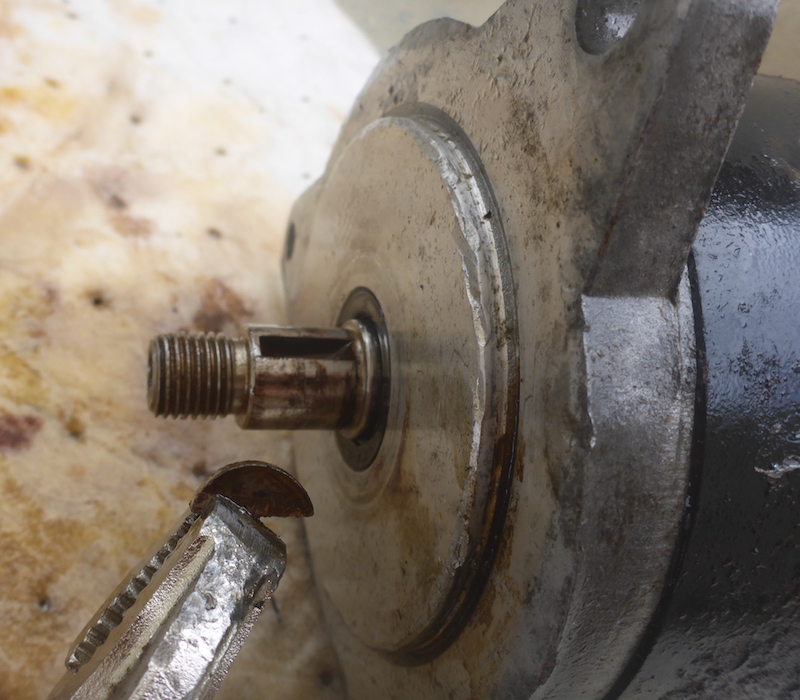
Looking at the parts detail, I knew I could not use screw driver to separate it because of the Thrust bearing AX2542 (part 485)
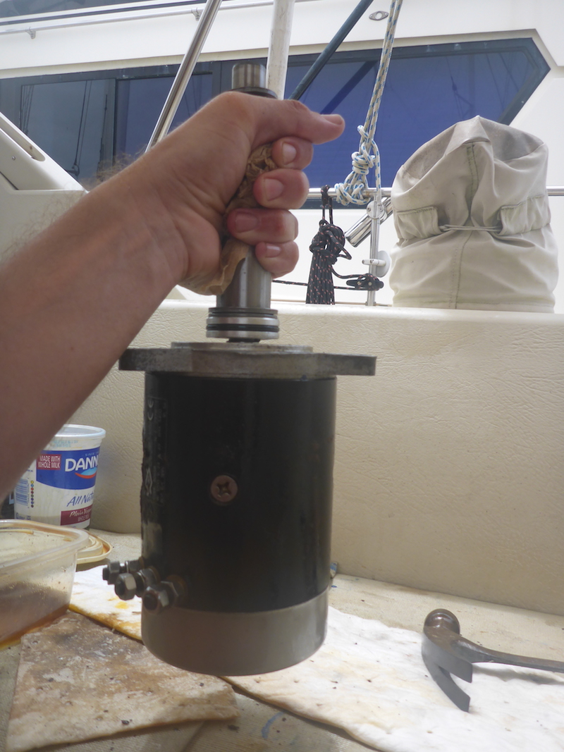
Picture 75
With one hand I hold a few centimeter above the ground
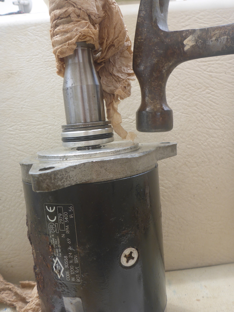
Picture 76
With the other hand, I used a hammer rotating every time
Every 5 or 6 knocks, I upside down the electric motor and Worm shaft to add penetrating oil
Note: I should have used an bronze hammer
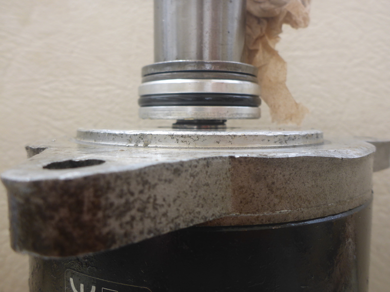
Picture 77
Starting to move
Picture 78
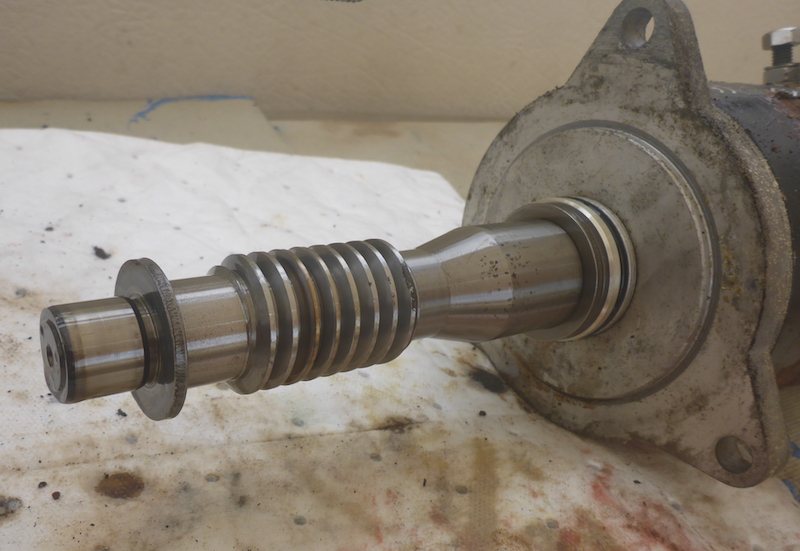
Finally off
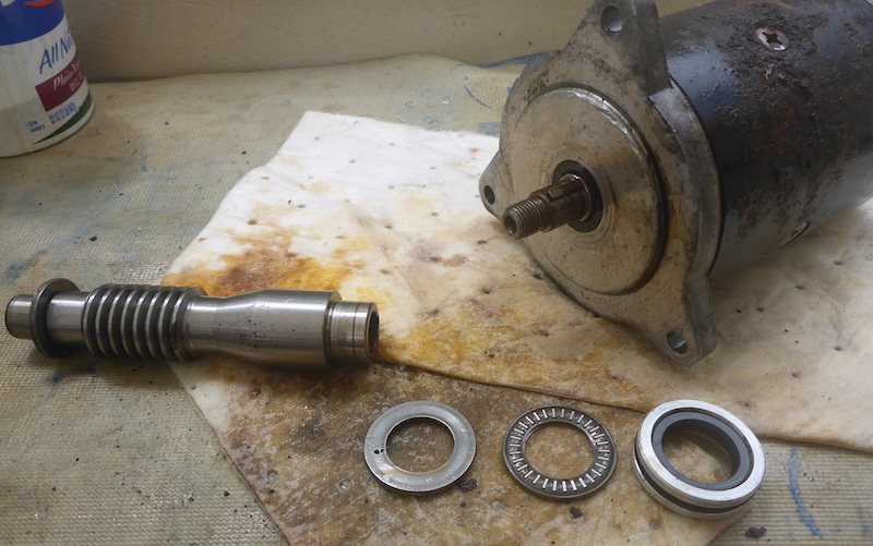
Picture 79
Looking at the parts from left to right
Worm (shaft) (Part 483)
Thrust ring CP32542 (Part 484)
Thrust bearing AX2542 (part 485)
Spacer (Part 486) which has 2 more parts in it
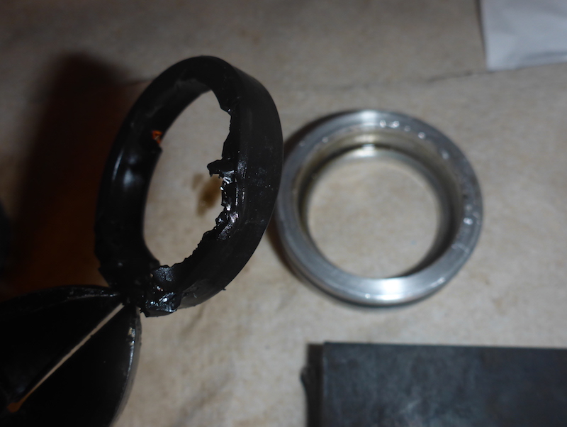
Picture 80
In the "Spacer" (Part 486), there is a 25-35-7 Oil Seal (Part 291)
Picture 81
And an O Ring 4143 (Part 487)
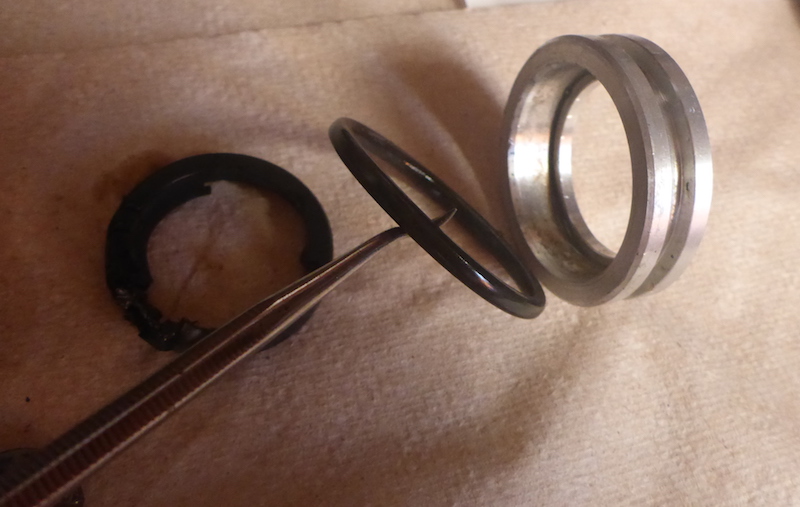
Picture 82
Removing the Round key 4x6.5 (Part 350)
Picture 83
Take reference of the electric motor specification

|
Next: Part 10
|
|
Part 1 10 Pictures from 01 to 7
Part 2 17 Pictures from 8 to 24
Part 3 8 Pictures from 25 to 32
Part 4 15 Pictures from 26 to 40
Part 5 8 Pictures from 41 to 48
Part 6 7 Pictures from 49 to 55
Part 7 13 Pictures from 56 to 68
Part 8 5 Pictures from 69 to 73
Part 9 10 Pictures from 74 to 83
Part 10 4 Pictures from 84 to 87
Part 11 7 Pictures from 88 to 94
Part 12 6 Pictures from 95 to 100
Part 13 8 Pictures from 100 to 107
Part 14 6 Pictures from 108 to 114
Part 15 15 Pictures from 115 to 129
Part 16 16 Pictures from 130 to 145 |
Part 17 3 Pictures from 146 to 148 Putting key back on Electric motor shaft
Part 18 8 Pictures from 149 to 156
Part 19 12 Pictures from 157 to 168
Part 20 9 Pictures from 169 to 177
Part 21 16 Pictures from 178 to 193
Part 22 15 Pictures from 194 to 208
Part 23 19 Pictures from 209 to 217
Part 24 20 Pictures from 218 to 239
Part 25 5 Pictures from 240 to 244
Part 26 3 Pictures from 245 to 247
Part 27 6 Pictures from 248 to 253
Part 28 4 Pictures from 254 to 258
Part 29 7 Pictures from 259 to 266
Part 30 12 Pictures from 267 to 278
Part 31 16 Pictures from 279 to 294
Part 32 6 Pictures from 295 to 300
|