NIKIMAT


Amel Super Maramu 2000
|
Lofrans Tigres Windlass Overhaul Part 21: 16 Pictures from 178 to 193 Adding seals back on Cover and Body |
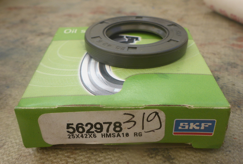
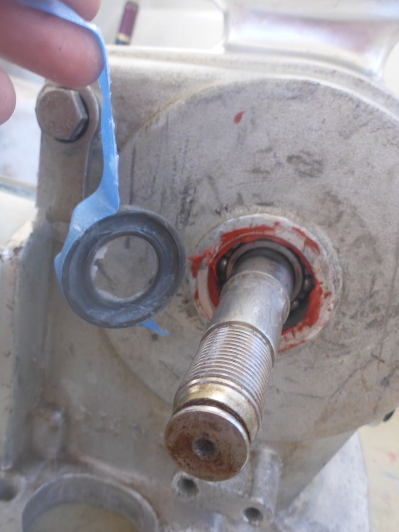
Picture 178
Adding the oil Seal 25-42-6 (Part 319)
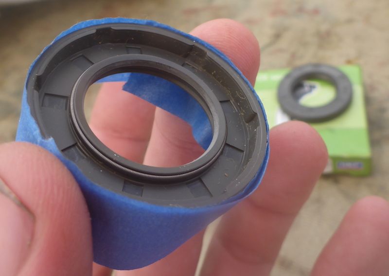
Picture 179
As previously explained, not sure if the TRV would be compromised if there was grease outside, I put some blue tape
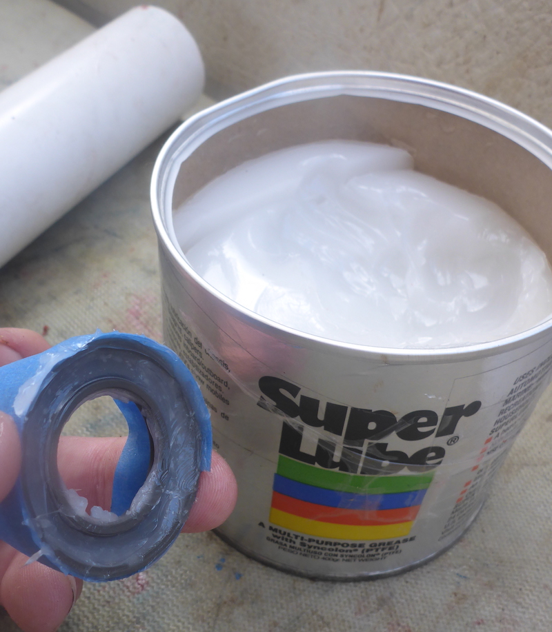
Picture 180
greased the inside
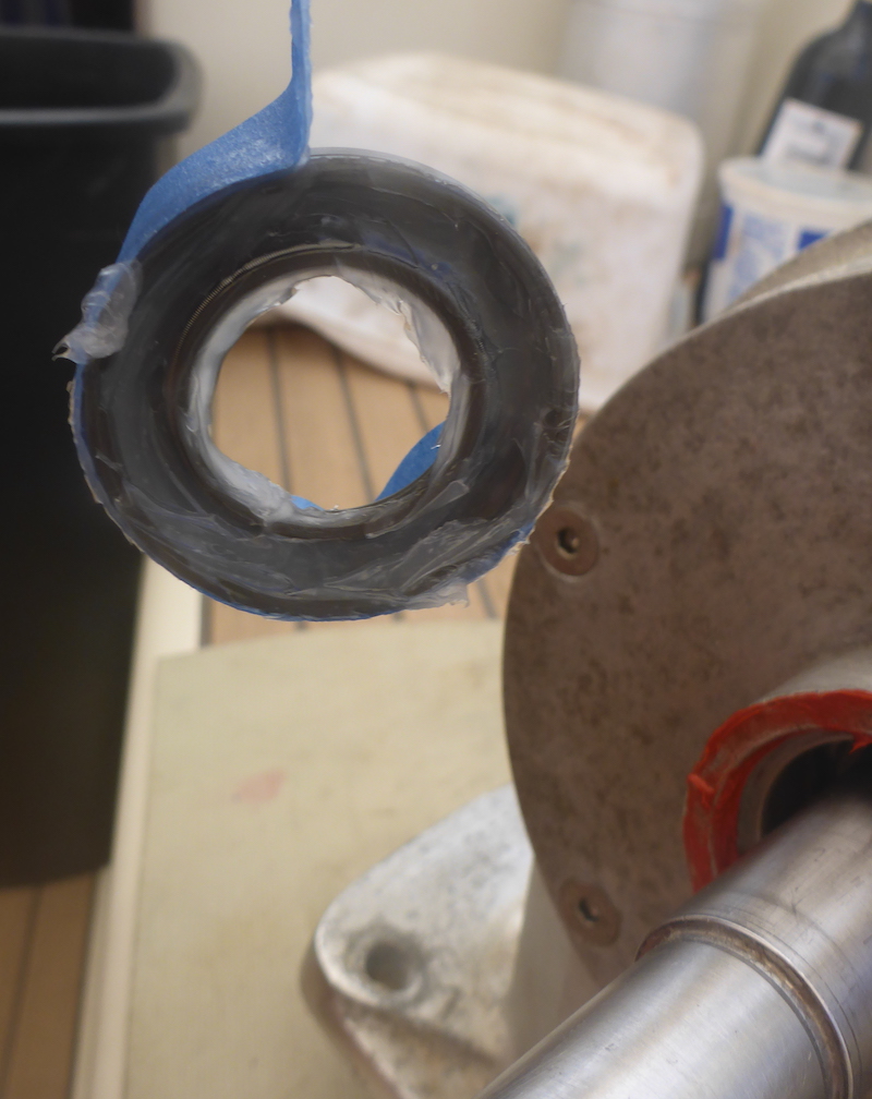
Picture 181
Removed the tape
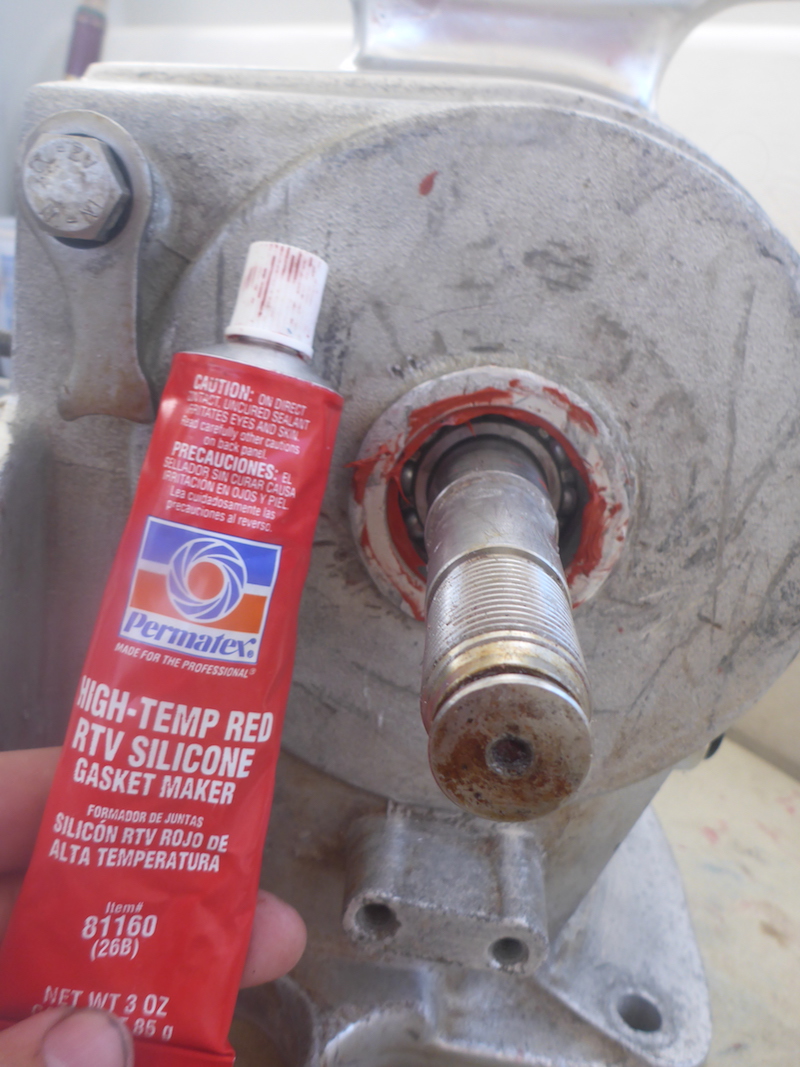
Picture 182
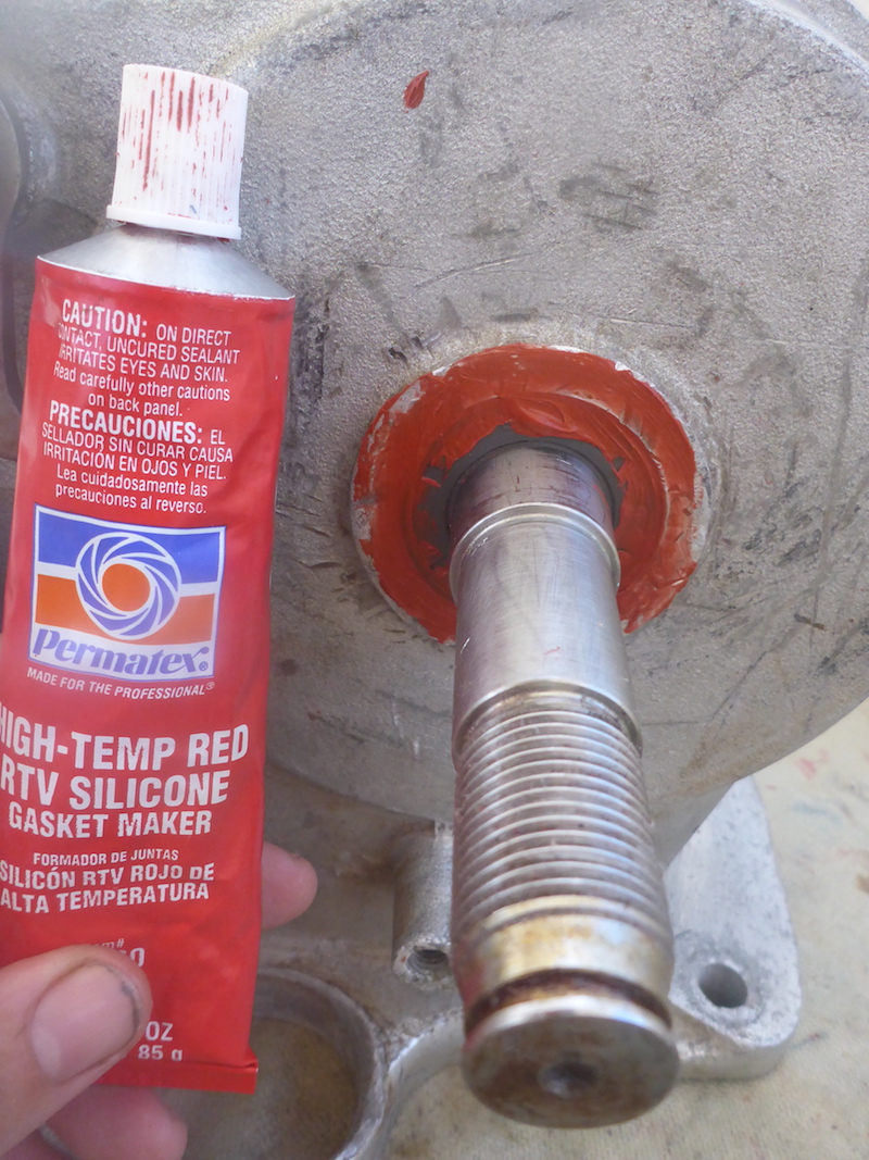
Put RTV, normally I would use the "Blue", but I run out
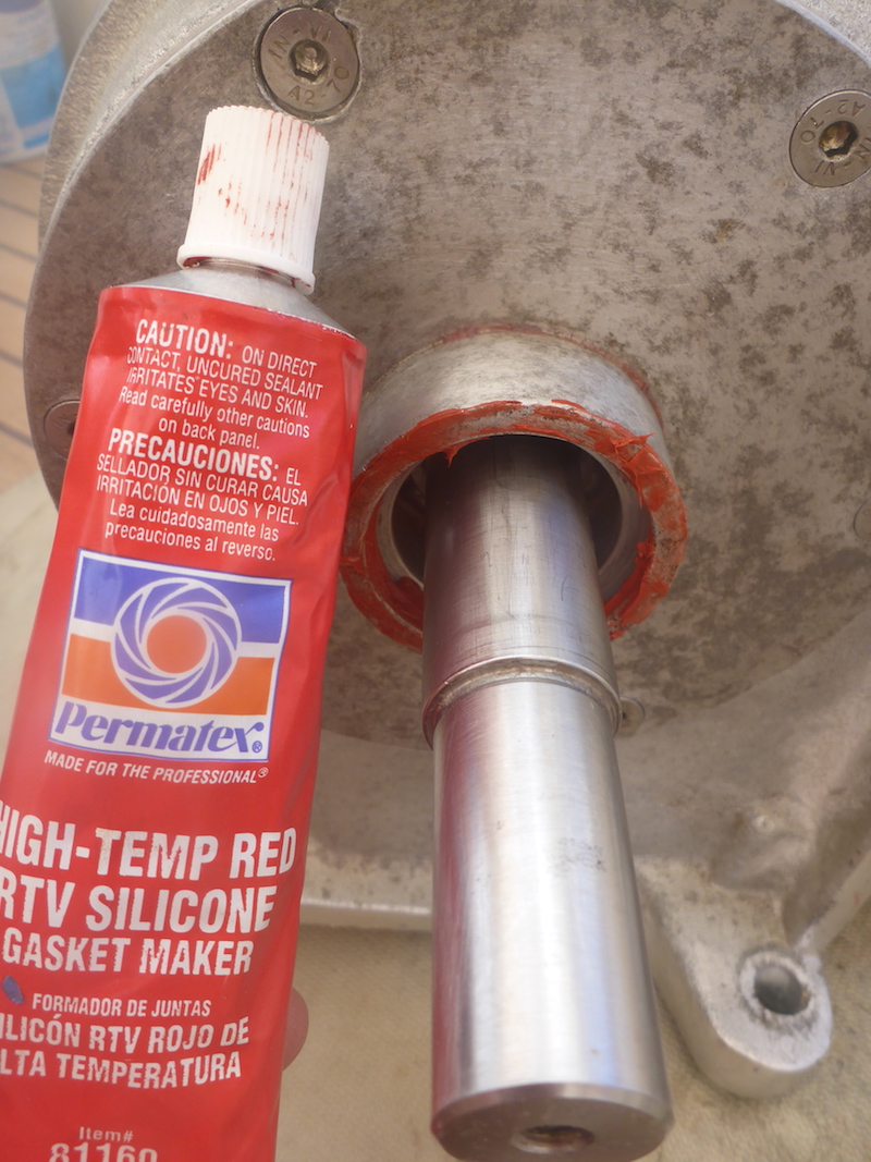
Picture 183
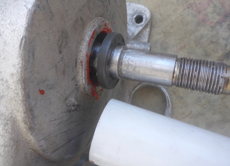
Sliding the oil Seal 25-42-6 (Part 319) and with a PVC pipe will set it in
Picture 184
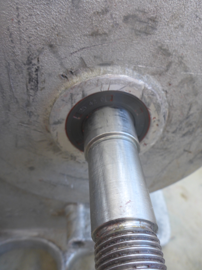
Set in
Picture 185
I put some more RTV around and cleaned the excess
Picture 186
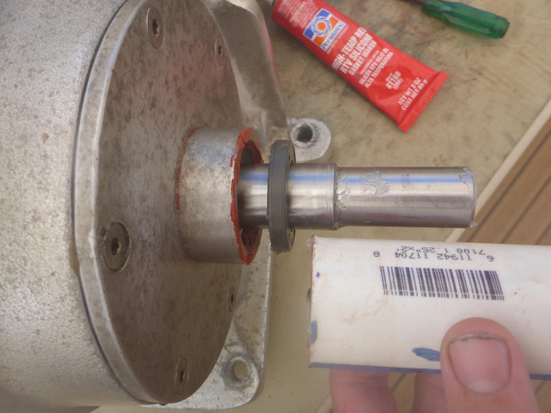
Now on the other side the other oil Seal 25-42-6 (Part 319)
Picture 187
For this one, I will use a wider PVC pipe as there is no lip to hold/stop the oil Seal 25-42-6 (Part 319)
Picture 188
RTV
Picture 189
Grease inside
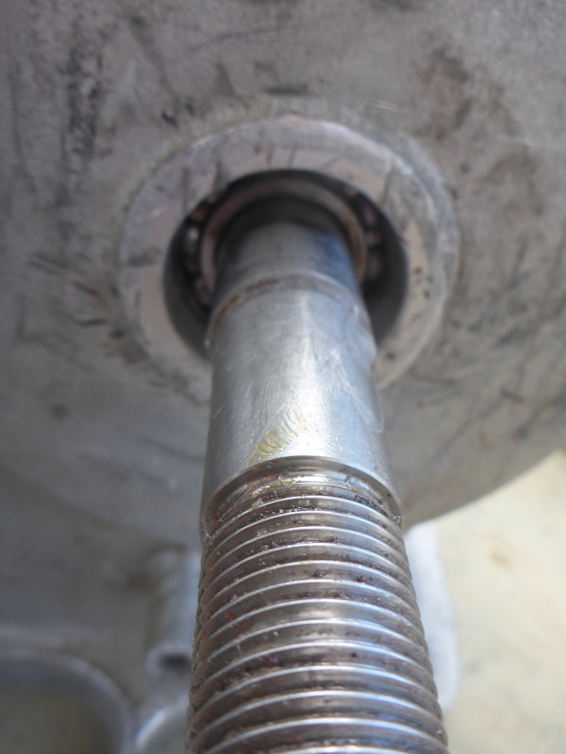
Picture 190
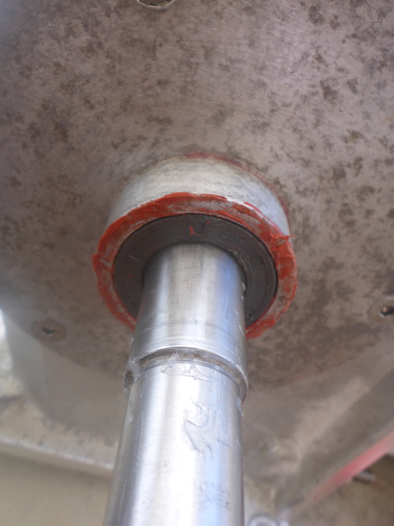
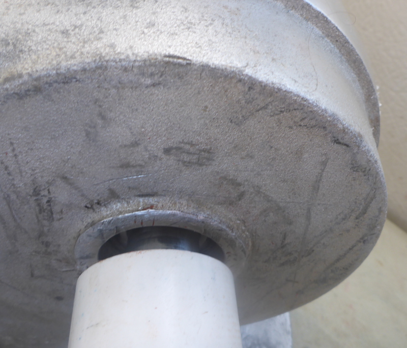
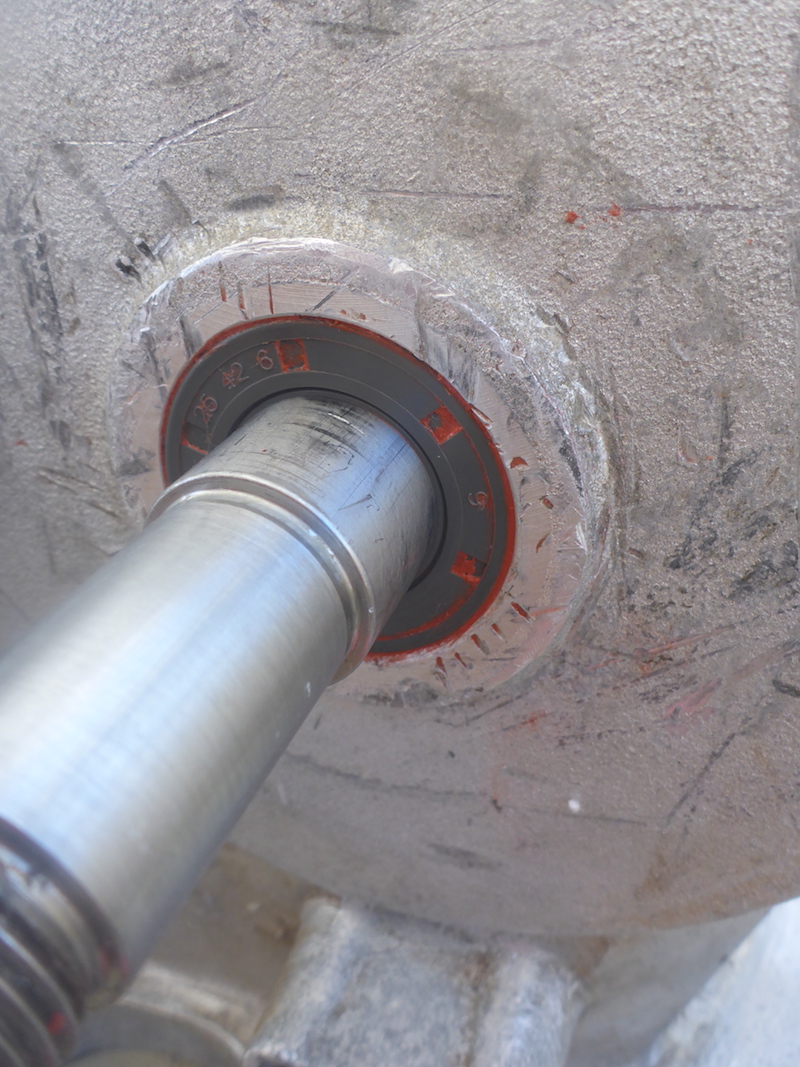
oil Seal 25-42-6 (Part 319) pushed on the shaft then using the wider PVC pipe push in flat
Picture 191
Now in
Picture 192
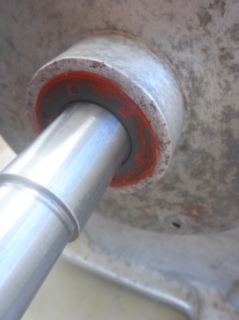
More RTV
Picture 193
Then clean
|
Next: Part 22
|
|
Part 1 10 Pictures from 01 to 7
Part 2 17 Pictures from 8 to 24
Part 3 8 Pictures from 25 to 32
Part 4 15 Pictures from 26 to 40
Part 5 8 Pictures from 41 to 48
Part 6 7 Pictures from 49 to 55
Part 7 13 Pictures from 56 to 68
Part 8 5 Pictures from 69 to 73
Part 9 10 Pictures from 74 to 83
Part 10 4 Pictures from 84 to 87
Part 11 7 Pictures from 88 to 94
Part 12 6 Pictures from 95 to 100
Part 13 8 Pictures from 100 to 107
Part 14 6 Pictures from 108 to 114
Part 15 15 Pictures from 115 to 129
Part 16 16 Pictures from 130 to 145 |
Part 17 3 Pictures from 146 to 148 Putting key back on Electric motor shaft
Part 18 8 Pictures from 149 to 156
Part 19 12 Pictures from 157 to 168
Part 20 9 Pictures from 169 to 177
Part 21 16 Pictures from 178 to 193
Part 22 15 Pictures from 194 to 208
Part 23 19 Pictures from 209 to 217
Part 24 20 Pictures from 218 to 239
Part 25 5 Pictures from 240 to 244
Part 26 3 Pictures from 245 to 247
Part 27 6 Pictures from 248 to 253
Part 28 4 Pictures from 254 to 258
Part 29 7 Pictures from 259 to 266
Part 30 12 Pictures from 267 to 278
Part 31 16 Pictures from 279 to 294
Part 32 6 Pictures from 295 to 300
|